Electrical components are the unsung heroes of our HVAC systems, refrigeration units, and industrial machinery. They work tirelessly behind the scenes to switch power on and off, ensuring your environment remains comfortable and your operations run smoothly. Among these components, the definite purpose contactor stands out as a critical device for handling high-current loads efficiently.
If you are a technician, facility manager, or DIY enthusiast looking to replace or install a contactor, understanding the wiring nuances between different pole configurations is essential. Incorrect wiring can lead to equipment failure, safety hazards, or expensive downtime.
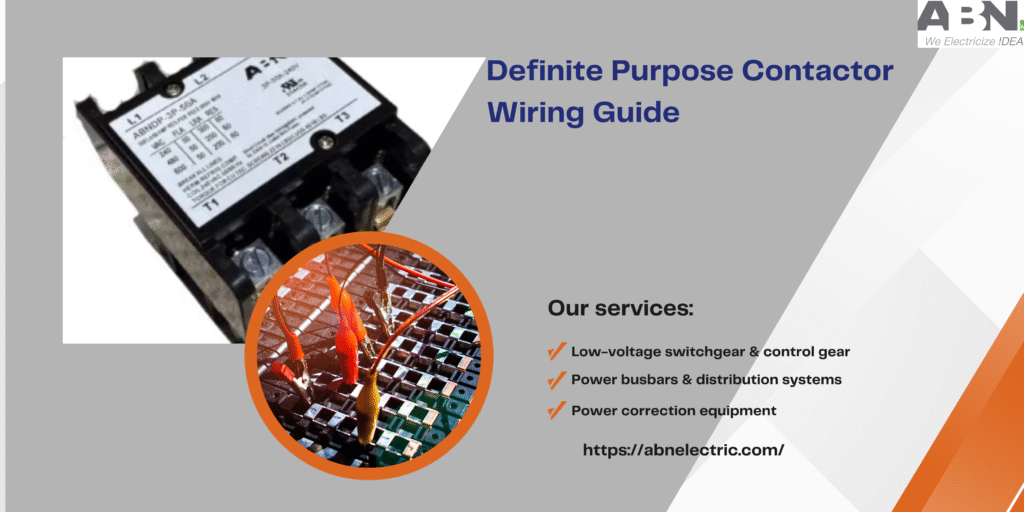
This guide provides a comprehensive overview of how to wire 1, 2, 3, and 4 pole models, specifically highlighting the robust features of the ABN-DP series. We will walk you through the basics of what these devices do, how to distinguish between different poles, and the specific wiring steps for each type.
What is a Definite Purpose Contactor?
A definite purpose contactor is an electrically controlled switch used for switching an electrical power circuit. Unlike general-purpose contactors, which are designed for a wide variety of applications, definite purpose contactors are engineered for specific applications—most commonly in the heating, ventilation, air conditioning, and refrigeration (HVACR) industry.
These devices are designed to handle the high inrush currents typical of motors and compressors. When your thermostat calls for cooling, it sends a low-voltage signal to the contactor’s coil. This magnetic coil energizes, pulling the contacts together to complete the high-voltage circuit, thus powering up the compressor and fan.
The ABN-DP series, for example, is built for maximum dependability with a life cycle exceeding 250,000 electrical and 1,000,000 mechanical operations. Whether you are dealing with a 20A residential unit or a heavy-duty 90A industrial system, choosing a high-quality definite purpose contactor ensures longevity and safety.
Key Safety Precautions Before Wiring
Before we dive into the specific wiring configurations for 1, 2, 3, and 4 pole models, safety must be the priority. Working with electricity carries inherent risks, and neglecting safety protocols can be fatal.
- Disconnect Power: Always shut off the main power supply at the breaker panel before opening any equipment. Use a multimeter to verify that no voltage is present.
- Label Wires: If you are replacing an existing unit, take a photo or label the wires before disconnecting them. This simple step can save hours of frustration.
- Check Ratings: Ensure the replacement definite purpose contactor matches the voltage and amperage ratings of the original equipment. The coil voltage (e.g., 24V, 120V, 240V) must match your control circuit.
- Inspect Connections: Loose connections generate heat, which is the enemy of electrical components. Ensure all terminal screws are tightened to the manufacturer’s torque specifications.
Wiring a 1-Pole Definite Purpose Contactor
The 1-pole definite purpose contactor is commonly found in residential air conditioning units. It is designed to break only one leg of the power supply to the load.
How it Works
In a 1-pole configuration, typically one leg of the power (L1) flows through the switched contact (T1), while the other leg (L2) flows through a “shunt” or a solid bus bar to the load side. This means that even when the contactor is off, voltage is still present at the motor or compressor on one side.
Wiring Steps
- Line Connections: Connect the incoming power wire (L1) to the line side terminal of the contactor.
- Shunt Connection: The second incoming power wire connects directly to the shunt bar (often labeled or visibly continuous).
- Load Connections: Connect the wire leading to the compressor or motor (T1) to the load side of the switched pole. The second load wire connects to the other side of the shunt.
- Coil Voltage: Connect the low-voltage control wires (usually 24V from the thermostat/furnace) to the coil terminals located on the sides of the contactor.
Wiring a 2-Pole Definite Purpose Contactor
A 2-pole definite purpose contactor is widely used in residential and light commercial HVAC systems. Unlike the 1-pole version, this device breaks both legs of the power supply, offering a higher level of safety because no voltage remains at the load when the contactor is de-energized.
How it Works
Both incoming power lines (L1 and L2) are switched. When the coil energizes, two separate sets of contacts close simultaneously, sending power to T1 and T2.
Wiring Steps
- Line Connections: Connect your incoming power lines to the terminals marked L1 and L2 on the supply side.
- Load Connections: Connect the wires leading to your component (compressor/fan) to the terminals marked T1 and T2 on the load side.
- Coil Connection: Attach your control circuit wires to the coil terminals.
- Verification: Double-check that L1 corresponds to T1 and L2 corresponds to T2 to maintain proper phasing, although phase rotation is less critical in single-phase applications compared to three-phase.
Wiring a 3-Pole Definite Purpose Contactor
When moving into commercial and industrial applications involving three-phase motors, you will encounter the 3-pole definite purpose contactor. These are essential for managing three-phase power supplies, which are more efficient for heavy-duty machinery.
How it Works
This unit switches three separate power legs (L1, L2, L3) simultaneously. It is crucial for three-phase motors because losing one phase (single-phasing) while the motor is running can cause rapid overheating and failure.
Wiring Steps
- Line Side: Connect the three incoming power phases to terminals L1, L2, and L3.
- Load Side: Connect the outgoing motor leads to T1, T2, and T3.
- Coil Wiring: Connect the control voltage to the coil terminals. Note that in commercial settings, coil voltages might be higher (120V or 240V) compared to residential systems.
- Phase Rotation: Ensure that the wiring sequence matches the required rotation of the motor. If the motor spins backward, swap any two leads on the load side (e.g., swap T1 and T2).
Wiring a 4-Pole Definite Purpose Contactor
The 4-pole definite purpose contactor is less common but highly useful in specific scenarios. It is often used in applications requiring the switching of a neutral line alongside three phases, or for controlling two separate single-phase loads simultaneously.
How it Works
This device has four sets of contacts that open and close together. It provides isolation for four separate lines.
Wiring Steps
- Identify Application: Determine if you are switching a neutral (4th pole) or controlling auxiliary equipment.
- Line and Load: Similar to the 3-pole setup, connect your supply lines to L1, L2, L3, and L4. Connect the corresponding load wires to T1, T2, T3, and T4.
- Coil: Connect the control circuit to the coil terminals.
- Auxiliary Use: If the 4th pole is used for an auxiliary control circuit rather than a power load, ensure the current rating of that circuit does not exceed the contactor’s pole rating.
The ABN-DP Series Advantage
When selecting a replacement, quality matters. The ABN-DP series of definite purpose contactors offers distinct advantages over standard models. These units act as an ideal one-for-one replacement for Furnas DP contactors and meet the stringent ARI 780/790 standards.
One specific feature of the ABN-DP series is the use of high arc-resistant phenolic resin material. This material holds the stationary terminals and positions the actuator and magnet assembly. This construction provides much stronger endurance and insulating ability than normal contactors, which is critical when the device is subjected to the heat and stress of frequent cycling.
Additionally, the internal construction uses engineered compounds designed to provide excellent mechanical life, even in demanding applications. Whether you need a 1P, 1P+N, 2P, 3P, or 4P configuration, these units offer a wide range of coils and optional terminal connections to fit your specific setup.
Frequently Asked Questions (FAQ)
How do I know if my definite purpose contactor is bad?
Common signs of a failing contactor include a loud buzzing or chattering noise, a compressor or fan that won’t start even when the thermostat calls for it, or visible signs of burning/pitting on the contacts. A multimeter can be used to check for continuity across the closed contacts and resistance across the coil.
Can I replace a 1-pole contactor with a 2-pole contactor?
Yes, in most cases, you can upgrade from a 1-pole to a 2-pole definite purpose contactor. This is often considered an upgrade because it breaks both legs of power, increasing safety. However, you must ensure the amperage and coil voltage ratings are identical.
What is the difference between a contactor and a relay?
While both are switches, a definite purpose contactor is designed to handle high-current loads (like motors and compressors), typically above 10 amps. Relays are generally used for lower-current control circuits. Contactors also typically have a different physical construction to suppress the electrical arc created when opening a high-load circuit.
Does the coil voltage matter?
Absolutely. The coil voltage must match the control voltage provided by your system (e.g., your furnace board or thermostat). Common coil voltages include 24V, 120V, 208/240V, and 480V. Installing a 24V coil on a 120V circuit will instantly burn out the coil.
Why does the ABN-DP series use phenolic resin?
Phenolic resin is used for its superior heat resistance and electrical insulation properties. In a definite purpose contactor, electrical arcs can occur during switching. The phenolic resin housing contains these arcs safely and prevents the heat from deforming the unit, ensuring a longer operational life.
Ensuring Long-Term Reliability
Wiring a definite purpose contactor correctly is the first step toward a reliable HVAC or industrial system. However, the quality of the component you install is just as important as the installation itself.
If you are unsure about which model fits your needs or need specific technical advice regarding the ABN-DP series, professional guidance is always the best route. Ensuring you have the correct amperage, coil voltage, and pole configuration will save you time and money in the long run.
For more information on the ABN-DP series or to find the perfect replacement for your system, please don’t hesitate to Contact Us. Our team is ready to assist you with high-quality solutions for all your electrical distribution needs.